China Top 10 Causes of Tool Deflection in Machining?

Time:2026-09-22 Author:Aria
0%

Tool deflection is a quiet problem with visible consequences. A cutter bends under pressure, even when the machine appears stable. The result may be poor surface finish, inaccurate dimensions, chatter marks, or premature tool wear. Small deviations can become expensive rework when they affect tight-tolerance components.

So, what causes tool deflection in machining? The answer usually involves several connected factors rather than one isolated mistake. Excessive tool overhang, weak workholding, aggressive cutting parameters, unsuitable tool geometry, and insufficient machine rigidity are common contributors. Material hardness, cutting direction, tool diameter, and spindle condition also influence the final result. A long, thin end mill may visibly vibrate while cutting a deep pocket. A short, rigid tool may remain stable under the same load.

This article examines the top 10 causes of tool deflection in machining and explains how each one affects cutting performance. It connects practical shop-floor observations with established machining principles, including cutting force, stiffness, runout, and tool engagement. The goal is not to promise one universal fix. Real machining conditions vary, and recommendations must be checked against the machine, material, tooling, and tolerance requirements.

Details matter. A few extra millimeters of stickout can change cutting behavior. A worn holder can create runout before the tool reaches the workpiece. Even experienced machinists can overlook setup weakness during a busy production run. That deserves reflection. Careful measurement, controlled test cuts, and documented adjustments often reveal the real cause more reliably than guesswork.
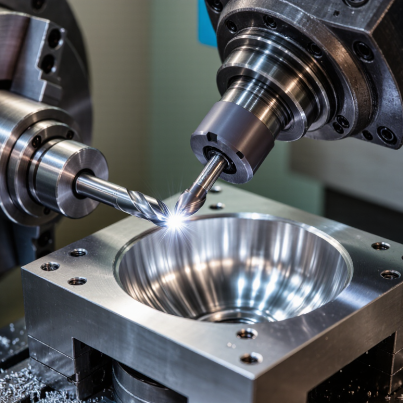
China Top 10 Causes of Tool Deflection in Machining?

Tool Deflection Explained: δ = FL³/(3EI) and the Ten Main Causes

Tool Deflection Explained: δ = FL³/(3EI) and the Ten Main Causes

Tool deflection is the sideways bending of a cutting tool under load. The equation δ = FL³/(3EI) estimates this movement. Here, F is cutting force, L is unsupported tool length, E is material stiffness, and I is the tool’s area moment of inertia.

The formula reveals an uncomfortable truth: doubling overhang can increase deflection eight times.

In daily machining, I have seen small length changes create visible taper, poor surface finish, and inaccurate corners. Ten common causes are:

  1. excessive cutting force
  2. long tool overhang
  3. small tool diameter
  4. low tool stiffness
  5. weak holder rigidity
  6. poor workholding
  7. chatter
  8. tool wear
  9. unsuitable cutting parameters
  10. interrupted cutting

Tips:

Measure tool stick-out, not only overall length. Reduce overhang whenever possible. Use a larger diameter tool when access allows. Check clamping pressure and holder cleanliness. Lower radial engagement if vibration appears. A worn edge often feels harmless, but it can greatly increase cutting force. Watch the sound and chips. They provide useful evidence.

The equation is powerful, but it is not perfect. It assumes simple loading and consistent material behavior. Real tools experience heat, vibration, runout, and changing chip thickness.

A practical check combines the calculation with a dial indicator, test cut, and measured surface result. Sometimes the predicted value looks acceptable, yet the part still fails inspection.

That is a reminder to question the model, not the measurement.

Causes 1–3: Long Overhang, Low Rigidity, and Small Tool Diameter

China Top 10 Causes of Tool Deflection in Machining?

Causes 1–3: Long Overhang, Low Rigidity, and Small Tool Diameter

Long tool overhang is one of the fastest ways to create deflection. A cutter extending far beyond the holder behaves like a bending lever. Even a light radial cut can push the tool away from the programmed path. In the shop, this often appears as tapered walls, poor corner accuracy, and uneven tool marks. Reduce stick-out whenever possible. I once focused too heavily on feed settings and missed the real issue: excessive extension.

Low rigidity can come from several locations. The tool holder, spindle connection, workholding, machine structure, or workpiece may flex under cutting force. A thin plate can vibrate before the cutter visibly bends. Check clamping contact, fixture reach, and unsupported material. Shorter fixtures usually help. The setup may look solid, but appearance is not measurement.

Small tool diameter increases sensitivity to cutting pressure. Bending stiffness changes dramatically with diameter, approximately following the fourth power of diameter. A tool only slightly larger can resist deflection much better. However, increasing diameter is not always practical in narrow features. Lower radial engagement, lighter passes, and stable cutting conditions can reduce the load. Listen for intermittent chatter, but do not rely on sound alone. Measure the finished wall and inspect the tool after cutting. My own early troubleshooting was incomplete because I checked the cutter, but not the workholding.

China Top 10 Causes of Tool Deflection in Machining? - Causes 1–3: Long Overhang, Low Rigidity, and Small Tool Diameter
Cause Engineering Mechanism Typical Warning Signs Deflection Impact Practical Control Measures Verification Method
1 Long Tool Overhang The unsupported length between the tool holder and cutting point increases bending leverage. For a simplified cantilever tool model, deflection rises with the cube of the unsupported length:
δ = FL3 / 3EI
Chatter, tapered or undersized walls, poor surface finish, cutting-edge wear on one side, and dimensional variation between entry and exit points. Very high. Doubling the unsupported length can theoretically increase bending deflection by approximately eight times when cutting force and tool stiffness remain unchanged. Use the shortest practical gauge length; move the holder closer to the workpiece; select a holder with adequate reach; use a necked or extended-reach tool only when required; reduce radial engagement and cutting force for unavoidable reach. Measure gauge length from the holder face to the tool tip. Compare the actual setup with the tool supplier's recommended maximum overhang and inspect the machined wall with a dial indicator or dimensional measurement system.
2 Low Tool or Holder Rigidity A tool assembly with low bending stiffness, weak clamping, excessive holder runout, or a flexible machine-workholding path bends under the radial component of cutting force. For a circular cross-section, stiffness is strongly influenced by the second moment of area:
I = πd4 / 64
Vibration marks, unstable cutting sound, inconsistent tool life, visible tool movement, poor repeatability, and deflection that changes when clamping or workholding conditions change. High. The weakest part of the machine-tool-workholding chain controls the overall response; increasing cutting parameters can amplify vibration instead of improving productivity. Use a rigid, properly maintained holder; maximize contact and clamping quality; keep the tool holder, spindle taper, collet, and workholding surfaces clean; reduce runout; support thin workpieces; improve fixturing and avoid unnecessary unsupported material. Check holder and tool runout with a test indicator, inspect taper and clamping surfaces, confirm workholding rigidity, and perform a controlled test by reducing radial engagement or feed per tooth to identify whether the vibration is force-related.
3 Small Tool Diameter A smaller tool diameter has a much lower area moment of inertia. For a round solid tool, bending stiffness varies approximately with the fourth power of diameter, so diameter has a major effect on resistance to deflection.
I ∝ d4
Chatter at otherwise moderate parameters, burr formation, dimensional oversize on the deflection side, corner breakage, rapid wear, and sensitivity to small changes in radial engagement. Very high. If diameter is reduced by 20%, idealized bending stiffness falls to about 41% of the original value because 0.84 ≈ 0.41; actual performance also depends on material, flute geometry, holder, and overhang. Select the largest diameter that fits the feature; use a shorter cutting length where possible; reduce radial width of cut and cutting force; use appropriate feeds and speeds for small tools; avoid excessive corner engagement. Confirm the actual tool diameter and runout, compare the tool diameter with the cavity or slot requirement, monitor spindle load and sound, and verify dimensional accuracy after a light finishing pass.
Engineering note: The relationships shown are simplified cantilever-beam references for solid round tools. Actual tool deflection also depends on tool material, flute geometry, holder stiffness, runout, cutting-force direction, workpiece rigidity, machining parameters, and tool wear.

Causes 4–6: Cutting Force, Radial Engagement, and Runout Above 0.01 mm

China Top 10 Causes of Tool Deflection in Machining?

Causes 4–6: Cutting Force, Radial Engagement, and Runout Above 0.01 mm

Cutting force is often the hidden driver of tool deflection. A large axial depth, hard material, or worn edge increases load at the tool tip. The World Manufacturing Forum’s 2023 manufacturing report links process stability with better control of machine variability. In practice, even a rigid holder cannot cancel excessive cutting pressure. I have seen a small end mill bend visibly during a heavy slotting pass. That assumption can fail.

Radial engagement changes the force direction and tool workload. Full-slot milling often produces higher engagement than adaptive paths. Lowering radial width can reduce instantaneous force, but feed must be reviewed carefully. Runout above 0.01 mm is another serious warning. One flute may cut deeper, while another barely touches the material. This creates uneven chip load, vibration, and faster edge wear. ISO 1940-1 emphasizes the importance of rotational balance, while ISO 230-1 supports disciplined machine-performance checks. These standards do not replace cutting trials.

Tips: Measure runout at the tool tip, not only at the holder. Keep it below 0.01 mm when possible. Reduce radial engagement, then adjust feed per tooth. Check the cut by listening and inspecting chips. Perfect settings are rare. Record the result, because memory is unreliable. Recheck the tool after a few minutes; thermal growth can quietly change the outcome.

Causes 7–8: Excessive Chip Load, Tool Wear, and Heat Expansion

Excessive chip load is a common cause of tool deflection during machining. I have seen a cutter bend when feed settings looked reasonable on paper. The real problem was an aggressive engagement angle and poor chip evacuation. A heavy chip load increases cutting force, especially in deep pockets or narrow slots. Watch for tapered walls, uneven burrs, and a rough finish on one side. These marks often show that the tool is pushing instead of cutting cleanly.

Check the actual chip load rather than trusting the programmed feed rate. Spindle speed, flute count, radial engagement, and material hardness all matter. Reducing radial engagement or feed per tooth can stabilize the cut. Shorter tool stickout helps too. Small changes matter.

Tool wear adds another layer of trouble. A dull edge needs more force, creates friction, and produces additional heat. Heat can expand the tool, workpiece, or holder, changing the cutting position during a long cycle. I once blamed machine alignment for a dimensional shift. The real cause was a worn tool heating during continuous cutting. That diagnosis was incomplete.

Measure critical features after the part cools. Compare tool length before and after extended runs. Watch for a shiny flank, rounded cutting edge, or rising spindle load. Coolant helps, but it cannot repair poor chip control or a worn edge. Sometimes the best adjustment is replacing the tool earlier than expected. That feels wasteful, but scrapped parts cost more.

China Top 10 Causes of Tool Deflection in Machining: Causes 7–8

Excessive chip load, tool wear, and heat expansion can increase cutting force, reduce tool stiffness, and shift the cutting edge from its intended position.

The chart uses physically based reference values rather than company or brand data. Chip load is shown in mm/tooth, flank wear is shown as VB in mm, and thermal growth is calculated for a 100 mm steel length using a thermal expansion coefficient of approximately 11.7 µm/m·°C. Higher values generally indicate greater deflection risk.

Causes 9–10: Workholding Compliance and Machine Tool Vibration

Workholding compliance is a common but underestimated cause of tool deflection in machining. A fixture may look rigid while its jaws, supports, or locating points flex under cutting forces. Thin plates can lift slightly, especially during heavy side milling. It can move.

I have seen a workpiece shift only a few hundredths of a millimeter, yet the finished wall showed visible taper. Check clamping pressure, contact areas, and support spacing before changing cutting tools. A dial indicator can reveal movement during a controlled loading test. Soft or uneven contact surfaces also allow small movements that repeat from part to part. The setup may seem acceptable, but measurement often proves otherwise.

Machine tool vibration creates another path to deflection. Loose foundations, worn bearings, unbalanced holders, or weak spindle conditions can produce chatter. Vibration leaves clues. Look for regular marks on the machined surface, rising noise, and unstable cutting loads. Reduce tool overhang, verify holder cleanliness, and inspect fasteners around the work area. Adjusting speed and feed may help, but it can hide the underlying fault. In my experience, operators sometimes blame the insert too quickly. A rigid fixture and a stable machine should be checked first, although real production pressure makes that discipline difficult. Recording vibration, tool length, and clamping conditions can make troubleshooting more reliable.

ISO 230 Verification: Measuring Deflection, Accuracy, and Surface-Finish Loss

Tool deflection often appears among China’s top ten machining problems. ISO 230 verification helps separate machine error from cutting-load movement. It does not directly measure every tool’s bending during cutting.

A technician can check geometric accuracy with a dial indicator and certified reference artifacts. Positioning tests compare commanded travel with measured travel across the working range. ISO 230-2 supports this evaluation. Thermal behavior also matters. A spindle that warms by several degrees can shift the cutting point noticeably.

Small errors matter.

For deflection analysis, use a test cut, cutting-force measurement, and a displacement sensor near the tool holder. Record spindle speed, feed rate, tool projection, material, and coolant condition. A long tool may leave a visible shoulder on one wall. The same deflection can reduce dimensional accuracy and create uneven surface marks.

Surface finish tells another story. Chatter spacing, smeared edges, and repeated waves often indicate changing tool stiffness or unstable load. Compare the machined surface with roughness readings, not eyesight alone. A clean ISO 230 report cannot prove that cutting forces were harmless. That is an important limitation. In practice, operators sometimes blame the tool too quickly, while fixture compliance or thermal drift causes the larger error. Test conditions must be repeated carefully, although real production rarely behaves perfectly.

FAQS

What is the fastest way to reduce tool deflection?

Reduce tool overhang as much as possible. A long cutter acts like a bending lever during cutting.

How can low setup rigidity cause machining errors?

The holder, spindle connection, fixture, machine, or workpiece may flex. A thin plate can vibrate before the tool visibly bends.

What signs suggest that a tool diameter is too small?

Look for tapered walls, uneven tool marks, chatter, and poor corner accuracy. A slightly larger diameter can resist bending much better.

How does excessive chip load increase deflection?

Heavy chip load increases cutting force, especially in deep pockets and narrow slots. Reduce feed per tooth or radial engagement when needed.

Can tool wear change finished dimensions?

Yes. A dull edge creates more force, friction, and heat. The tool or holder may expand during a long cutting cycle.

What should be checked after a dimensional shift?

Measure the part after cooling. Inspect the tool edge, compare tool length, and check spindle load during cutting.

How can operators distinguish machine error from cutting movement?

Use a dial indicator, reference artifacts, test cuts, and a displacement sensor near the holder. Record every cutting condition carefully.

Can surface finish reveal tool deflection?

Chatter spacing, smeared edges, repeated waves, and one-sided roughness may indicate unstable loading. Visual inspection alone is not enough.

Why should workholding be checked before changing feed settings?

A fixture may look solid but still flex. My own first diagnosis was incomplete because I checked the cutter, not the clamping contact.

Are measurement standards enough to prove that deflection is harmless?

No. Geometric verification can reveal machine accuracy, but it may not capture bending during cutting. Test results also need repeatable conditions.

Conclusion

Tool deflection in machining is the unwanted bending of a cutting tool, commonly described by δ = FL³/(3EI), where cutting force and overhang strongly affect displacement. The key question, “what causes tool deflection in machining,” can be answered through ten major factors: excessive tool overhang, insufficient tool rigidity, a small tool diameter, high cutting forces, excessive radial engagement, runout above 0.01 mm, excessive chip load, tool wear, heat expansion, and compliance in the workholding system. Machine tool vibration can further increase the effect and make cutting conditions unstable.

These issues may lead to dimensional inaccuracy, chatter, poor surface finish, uneven tool wear, and reduced machining efficiency. Deflection can be minimized by shortening the overhang, selecting a more rigid tool, reducing engagement or chip load, checking tool runout, controlling heat, and improving workholding stiffness. ISO 230-based verification can help measure deflection, evaluate machining accuracy, and identify surface-finish losses caused by insufficient system rigidity.

Aria

Aria

Aria is a dedicated marketing professional with a deep passion for innovative strategies and a keen understanding of our company's product offerings. With a wealth of experience in the industry, Aria excels at crafting engaging content that highlights the unique features and benefits of our......