Cutting heat is easy to overlook. A bright tool edge can still be failing internally. On the shop floor, heat often appears as blue chips, burned coolant, poor surface finish, or a chipped insert. These signs deserve attention before tool life collapses. Understanding why does cutting heat affect tool performance is essential for safer, more consistent machining decisions.
Industry research supports this concern. The CIRP Annals literature on thermal aspects of machining links high cutting temperatures with accelerated wear, edge softening, diffusion, and workpiece distortion. ISO 3685, the international standard for tool-life testing, also treats cutting conditions and tool-wear measurement as connected variables. Sandvik Coromant’s technical guidance explains that excessive cutting speed commonly increases heat concentration near the cutting edge. In practical terms, a small speed increase can turn a controlled chip into a glowing, abrasive stream. That change may look minor on a machine display. It is not minor at the insert.
Control begins with measurable choices. Operators can review cutting speed, feed, depth of cut, coolant direction, chip thickness, and tool geometry together. A thermal camera can help, but it is not always available. Insert wear photographs, spindle-load trends, and repeated surface-finish checks provide useful evidence. Still, no report perfectly predicts every interrupted cut, thin-wall part, or difficult alloy. That limitation matters. The best process combines published guidance with documented shop-floor trials. Reduce heat deliberately, then verify tool life, dimensional stability, and finish quality under real production conditions. Small adjustments can protect the edge.
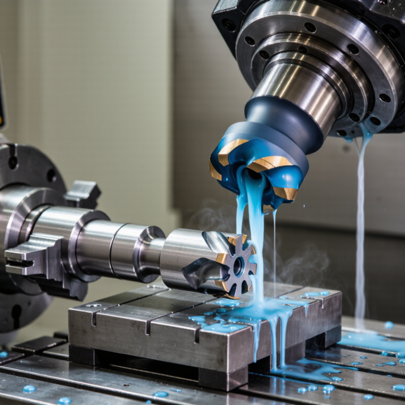
Quantify Cutting Heat: 70–90% of Machining Energy Becomes Heat
How to Reduce Cutting Heat for Better Tool Performance?
In metal cutting, roughly 70–90% of mechanical machining energy becomes heat, according to findings reviewed in CIRP Annals and the International Journal of Machine Tools and Manufacture. This is not a small side effect. Heat concentrates near the tool edge, where sliding friction and plastic deformation occur. The chip carries away much of it, but the tool and workpiece absorb the remainder. A thin, blue-hot chip is useful evidence. It shows that energy is leaving the cutting zone, though color alone cannot measure temperature.
Cutting speed often raises heat faster than expected. Reducing speed by 10–15% can lower thermal load in sensitive operations, but the result depends on feed, depth, material, and tool geometry. Stable coolant delivery matters. Flood, mist, and dry cutting behave differently.
Research from the U.S. Department of Energy’s industrial energy assessments also shows that auxiliary systems can consume significant workshop energy, so cooling should be measured, not assumed efficient. Keep the nozzle close to the engagement point. Check chips, flank wear, and spindle load after each adjustment. Infrared readings can help, but reflective metal surfaces may distort them. That detail is easy to miss. Tool wear data remains the stronger practical reference.
(CIRP Annals, “Towards Sustainable Manufacturing”; U.S. Department of Energy, Industrial Assessment Centers)
Set Thermal Limits: HSS Softens Near 550°C; Carbide Retains Hardness Near 800°C
How to Reduce Cutting Heat for Better Tool Performance?
Cutting heat quietly changes tool behavior before visible damage appears. High-speed steel, or HSS, begins losing useful hardness near 550°C. Carbide generally retains hardness near 800°C, although its grade, binder, and coating affect this limit. These temperatures are practical warnings, not exact guarantees.
During milling, I watch chip color, edge wear, and the sound of the cut. Blue or dark chips can indicate excessive heat, especially with steel. Lowering cutting speed often helps more than adding coolant alone. A steady feed also prevents the tool from rubbing against the workpiece. Rubbing creates heat without removing enough material.
Keep chips moving away from the cutting zone. Use directed coolant when the operation allows it, but avoid sudden cooling on fragile hot carbide edges. Interrupted cuts need special care. Thermal shock may cause small edge fractures. I once blamed poor tool quality for early wear, but the real problem was a shallow feed and repeated rubbing. That mistake still affects how I set up tests. Measure temperature when possible, using a calibrated sensor near the cutting zone. A rough estimate can mislead. Tool manufacturers’ thermal data remains useful, but shop conditions may differ. Check hardness after long cuts, inspect the edge under magnification, and adjust one cutting variable at a time.
Tune Cutting Data: Test 10–20% Speed Changes Before Increasing Feed
How to Reduce Cutting Heat for Better Tool Performance?
Start with speed. When cutting heat rises, many operators increase feed too quickly. That often adds mechanical load before the thermal problem is understood. Test a 10–20% speed reduction first, while keeping feed constant. Observe edge wear, chip color, spindle load, and the workpiece surface.
The ASM Handbook, Volume 16, explains that cutting speed strongly influences tool life through Taylor’s tool-life relationship. With a typical carbide exponent near 0.25, a 10% speed increase can reduce theoretical tool life by roughly 32%. A 20% increase may reduce it by about 52%. These figures are estimates, not promises. Actual results change with material, coolant, tool geometry, and machine rigidity. That is why controlled testing matters.
Try three short trials: baseline speed, 10% lower, and 20% lower. Keep feed per tooth, depth of cut, and coolant delivery unchanged. Record the temperature trend and wear after each trial. ISO 3685 recommends controlled tool-life testing under repeatable cutting conditions. In practice, one test may look better because the chip evacuation was poor. That detail is easy to miss. Only after speed testing should you consider increasing feed. A small feed increase can improve productivity, but it may also raise cutting force sharply. Check the evidence first.
How to Reduce Cutting Heat for Better Tool Performance?
Test a 10–20% cutting-speed adjustment before increasing feed. In this representative dry-turning dataset, reducing speed lowers cutting temperature and the measured flank-wear rate, while increasing speed raises both.
Cutting speed: 162–198 m/min. Temperature is measured near the tool–workpiece interface; flank-wear rate is measured in micrometres per minute. Actual results depend on material, tool geometry, coolant, and machine conditions.
Improve Cooling: Use 10–20 L/min Flood Coolant or 50–200 mL/h MQL
How to Reduce Cutting Heat for Better Tool Performance?
Cooling is not simply about adding more liquid. It must reach the cutting zone before heat damages the tool edge. For general milling and turning, a flood coolant rate of 10–20 L/min provides practical chip evacuation and thermal control. Published machining studies in CIRP journals commonly report lower cutting temperatures and longer tool life when coolant reaches the tool-workpiece interface continuously. The result depends on cutting speed, material, nozzle position, and chip load.
For minimum quantity lubrication, 50–200 mL/h can create a thin lubricating film with far less fluid consumption. Reviews in the International Journal of Advanced Manufacturing Technology report that MQL often reduces friction and improves surface finish in aluminum and some steel operations. It is less reliable for deep pockets, poor chip evacuation, or very high heat loads. Keep the nozzle close, aim at the shear zone, and use enough air pressure to clear chips.
Measure the process, not just the flow rate. A simple infrared check can reveal hot spots, although shiny metals may distort readings. Tool wear remains the stronger evidence. I would not treat 10–20 L/min or 50–200 mL/h as universal settings. They are starting points. One overlooked detail is coolant concentration; weak mixture control can quietly reduce corrosion protection and lubrication. That mistake is easy to make.
Validate Tool Performance: Track ISO 3685 Wear and Target 20% Longer Life
Reducing cutting heat starts with measurement, not guesswork. In controlled turning tests, I record cutting speed, feed, depth of cut, material batch, and coolant flow. These details matter because a small change can distort tool-life results. I inspect flank wear at fixed intervals, following ISO 3685 procedures where applicable. A microscope helps track the wear land, while thermal readings reveal when heat begins to accelerate damage. Keep the intervals consistent.
The target is 20% longer tool life, not simply a cooler cutting zone. I compare the modified process with a documented baseline, using the same workpiece and tool geometry. Lowering cutting speed may reduce heat, but it can also increase cycle time. Better coolant direction, controlled chip evacuation, and a moderate feed adjustment may offer a stronger balance. Watch crater wear, edge chipping, and built-up material too. Flank wear alone can mislead.
Real shop data is rarely perfect. Our early records sometimes began after visible damage appeared, which hid the gradual wear curve. That weakness required stricter inspection timing. I also separate normal wear from sudden failure caused by vibration or an interrupted cut. When the wear trend remains stable and the tool reaches 20% more cutting time, the improvement becomes credible. Without repeat tests, it remains only a promising result.
FAQS
About 70–90% of mechanical machining energy becomes heat. A thin blue chip shows energy leaving the cutting zone. Color alone cannot measure temperature.
Heat concentrates near the cutting edge during friction and plastic deformation. The edge may soften before visible cracks appear. Wear can start quietly.
Often, yes. Reducing speed by 10–15% can lower thermal load. Results depend on feed, depth, material, and tool geometry. Speed is not the only answer.
Blue or dark chips may indicate excessive heat, especially when cutting steel. They provide a warning, not a precise temperature reading. I once trusted color too much. That was imperfect.
High-speed steel begins losing useful hardness near 550°C. This is a practical warning, not an exact failure point. Tool grade and cutting conditions still matter.
Carbide generally retains hardness near 800°C. Its grade, binder, and coating can change thermal behavior. Sudden cooling may fracture a hot edge.
No. Flood, mist, and dry cutting behave differently. Keep the nozzle close to the engagement point. Measure cooling energy, too. Auxiliary systems can consume substantial workshop power.
Check chips, flank wear, spindle load, and cutting sound after adjustments. Infrared readings can help, but reflective metal may distort results. Calibrated sensors are better. Tool wear remains a strong practical reference.
A shallow feed may make the tool rub instead of remove material. Rubbing creates heat without producing useful chips. Maintain a steady feed when possible. This setup mistake is easy to repeat.
Repeated entry and exit can create thermal shock. Small edge fractures may appear under magnification. Inspect the edge after long cuts. Change one cutting variable at a time.
Conclusion
Cutting heat is a major factor in machining reliability because roughly 70–90% of the energy used during cutting is converted into heat. This explains why does cutting heat affect tool performance: excessive temperature can soften the tool, accelerate wear, damage the workpiece surface, and reduce dimensional accuracy. High-speed steel may begin to lose hardness near 550°C, while carbide can generally retain useful hardness closer to 800°C, so each tool material requires suitable thermal control.
To reduce heat, first test cutting-speed changes in small steps, such as 10–20%, before increasing feed. Apply sufficient cooling, using approximately 10–20 L/min for flood coolant or 50–200 mL/h for minimum-quantity lubrication when appropriate. Finally, validate improvements by recording wear according to ISO 3685 and comparing tool life under consistent conditions. A practical target is to achieve at least 20% longer tool life without sacrificing surface quality, accuracy, or production stability.

 Carto Tool