How to Fix Poor Dimensional Accuracy in Machining?

Time:2026-09-07 Author:Ethan
0%

Poor dimensional accuracy can quietly undermine an otherwise capable machining operation. A bore may measure correctly at the machine, then fail inspection after cooling. A shaft may vary by only 0.03 mm, yet prevent proper assembly. These small differences often reveal unstable processes, not careless operators. This guide explains how to fix poor dimensional accuracy in machining through practical inspection, machine evaluation, tooling control, and process improvement.

W. Edwards Deming, an influential quality-management expert, stated, “Quality comes not from inspection, but from the improvement of the production process.” His principle remains highly relevant on the shop floor. Measuring finished parts is necessary, but measurement alone cannot correct thermal growth, tool deflection, backlash, vibration, or incorrect workholding. Reliable results require calibrated instruments, controlled cutting conditions, and documented setup procedures. It also helps to compare measurements taken at different times, because temperature can change the result.

Look closely.

A practical investigation should begin with evidence. Record the machine, material batch, tool number, offset changes, coolant condition, and inspection temperature. Check whether the error repeats in one direction or appears randomly. A consistent error may indicate incorrect offsets or machine geometry. Random variation may suggest loose fixturing, worn tooling, unstable material, or an unreliable measurement method. Not every diagnosis will be correct on the first attempt. That is an important weakness to acknowledge. Even experienced teams can adjust the wrong variable when records are incomplete. By combining operator experience, metrology discipline, and controlled trials, manufacturers can turn dimensional problems into measurable process improvements.
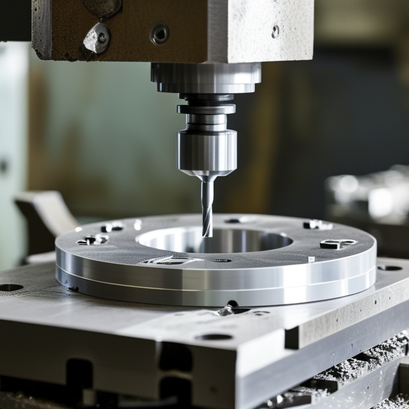
How to Fix Poor Dimensional Accuracy in Machining?

Measure the Error: Compare Size, Form, Position, and Runout to CAD

How to Fix Poor Dimensional Accuracy in Machining?

Measure the error before changing feeds, speeds, or tools. Align the part to the CAD datum system, then record temperature, probing method, and measurement uncertainty. A 20°C inspection environment matters because steel expands about 11 micrometres per metre for each 1°C change.

Compare the measured part with CAD in four ways. Size checks diameters, widths, and thicknesses. Form checks roundness, flatness, and straightness without relying on datums. Position checks the feature’s true location from the correct datum reference frame. Runout checks how a rotating surface behaves around its specified axis. A hole may have the correct diameter but still fail position. A shaft may pass size and fail total runout. ISO 14253-1 recommends considering measurement uncertainty before declaring conformity. ASQ quality-cost guidance commonly places poor quality near 15–20% of sales, showing why vague inspection results are expensive.

Tips: Export a color deviation map, but do not trust colors alone. Review the numerical values and tolerance zones. Use a calibrated CMM for critical features, and repeat questionable measurements. I have seen operators correct a tool offset when the real issue was datum selection. That mistake is easy to repeat. Inspect the same feature twice, preferably with a different setup. Record size, form, position, and runout separately. A single pass result proves very little.

How to Fix Poor Dimensional Accuracy in Machining? - Measure the Error: Compare Size, Form, Position, and Runout to CAD

Feature Error Category CAD Nominal / Requirement Tolerance Limit Measured Result Deviation from CAD Inspection Method Status Recommended Corrective Action
Mounting bore Size Ø25.000 mm ±0.020 mm Ø25.034 mm +0.034 mm Calibrated bore gauge FAIL Check tool wear and thermal growth; apply a verified tool offset before re-machining.
Overall length Size 80.000 mm ±0.050 mm 79.972 mm −0.028 mm Calibrated digital micrometer PASS Keep the current offset and monitor the next parts for dimensional drift.
Reference top face Form — Flatness Flatness zone ≤0.030 mm 0.046 mm +0.016 mm over limit CMM surface scan FAIL Verify workholding pressure, stock removal balance, and stress relief before finishing.
Precision journal Form — Cylindricity Cylindrical form zone ≤0.025 mm 0.018 mm 0.007 mm within limit Roundness and cylindricity measurement PASS Maintain the finishing pass and verify spindle condition at scheduled intervals.
Bolt-hole pattern Position — True Position Basic location from datums A|B ⌀0.050 mm ⌀0.072 mm ⌀0.022 mm over limit CMM true-position evaluation FAIL Recheck datum setup, fixture location pins, probing alignment, and coordinate-system rotation.
Side face to datum A Position — Perpendicularity 90° to datum A ≤0.040 mm 0.031 mm 0.009 mm within limit CMM angular and surface evaluation PASS Retain the current setup; verify vise alignment and datum cleanliness during setup.
Spindle-side outer diameter Runout — Radial Rotational axis reference ≤0.030 mm TIR 0.058 mm TIR 0.028 mm over limit Dial indicator over one full revolution FAIL Clean and reseat the workholding interface; inspect chuck jaws, collet condition, and spindle alignment.
Flange face Runout — Axial Face relative to rotational axis ≤0.040 mm TIR 0.036 mm TIR 0.004 mm within limit Dial indicator across face PASS Continue controlled facing operations and confirm the setup remains free of chips.
Inspection values are expressed in millimetres unless otherwise stated. TIR means total indicator reading. A failed result should be confirmed after checking measurement repeatability, temperature, datum setup, and fixture cleanliness.

Apply ISO 2768-1: General Linear Tolerances Range from ±0.1 to ±0.5 mm

How to Fix Poor Dimensional Accuracy in Machining?

Poor dimensional accuracy often begins with unclear drawing requirements. ISO 2768-1 helps control unspecified linear dimensions. Its general tolerance range commonly runs from ±0.1 to ±0.5 mm. However, the value depends on the nominal size and selected tolerance class. It is not one tolerance for every feature.

For example, under the medium class, dimensions from 0.5 to 3 mm may allow ±0.1 mm. Dimensions above 30 to 120 mm may allow ±0.3 mm. Dimensions above 120 to 400 mm may allow ±0.5 mm. These limits guide production, but they cannot replace a specific tolerance on a critical bore, slot, or mating surface. That mistake is easy to make. I have seen drawings rely on general tolerances when the assembly required tighter control.

Tips: Confirm the tolerance class before machining. Mark critical dimensions directly on the drawing. Check tool wear, workholding pressure, and machine temperature. Measure near the same datum used during setup. A warm machine may produce acceptable early parts and oversized later parts. Record inspection results at several stages, not only after finishing. If repeated errors remain, review the setup sequence and cutting conditions before blaming the machine. Sometimes the drawing needs revision, too.

Check Machine Geometry: Verify Accuracy with ISO 230-2 Test Methods

How to Fix Poor Dimensional Accuracy in Machining?

Poor dimensional accuracy often begins with machine geometry, not the cutting tool. A worn axis guide, loose coupling, or thermal drift can move the spindle away from its programmed position. The error may appear as a small step on a bore wall. It can also increase across a long travel.

ISO 230-2:2014 provides a practical method for checking linear positioning accuracy. Measure each axis with a calibrated laser interferometer or precision length standard. The test records positioning accuracy, repeatability, and reversal error. Run multiple bidirectional cycles at selected positions. Compare the results with the machine’s stated tolerance, not with assumptions. A 20-micrometre error may be acceptable for one process and unacceptable for another.

Measure after thermal stabilization. Record room temperature, machine temperature, feed rate, and measurement uncertainty. NIST’s Engineering Statistics Handbook emphasizes separating repeatability from reproducibility. That distinction matters during troubleshooting. Repeat the test on another day.

Look closely at the reversal points.

A large reversal error often indicates backlash or mechanical looseness. However, a clean ISO 230-2 result does not guarantee perfect parts. Fixturing, tool deflection, coolant temperature, and workpiece stress still affect accuracy. I have seen teams adjust compensation too early. The machine then passed the test but produced inconsistent bores. That was a mistake. Geometry should be checked first, compensation afterward. Keep the raw measurement files, calibration certificates, and environmental notes. Reliable decisions need traceable evidence.

Control Thermal Drift: Aluminum Expands 23.1 µm/m·°C with Temperature

How to Fix Poor Dimensional Accuracy in Machining?

Thermal drift is often the hidden cause of poor machining accuracy. Aluminum expands about 23.1 µm/m·°C, according to ASM Handbook, Volume 2. A one-meter aluminum part can grow 231 µm after a 10°C temperature rise. That is nearly a quarter millimeter. Small parts can suffer too. A 300 mm component changes about 69 µm under the same temperature shift. The cutting tool, fixture, and workpiece may also reach different temperatures. This creates unstable dimensions during inspection. I have seen accurate programs produce inconsistent parts after long production runs. The mistake was not always the CNC code. Sometimes, the room simply became warmer.

ISO 1:2016 establishes 20°C as the standard reference temperature for dimensional measurement. Keep the machine, material, gauges, and inspection room near that condition. Record temperature beside every critical measurement. Allow aluminum stock to stabilize before machining and inspection. Use coolant consistently, but monitor its temperature. Avoid measuring immediately after heavy cutting. That habit can produce misleading results. Compensation can help, but it should follow real temperature data, not guesswork.

Tips:

Measure the workpiece at several points. Compare morning and afternoon results. Check fixture contact areas for heat buildup. Use a calibrated probe and document its uncertainty. Review ASM Handbook thermal expansion values for the exact alloy. If stability remains poor, reduce cutting heat and extend material soak time. Perfect control is difficult. Ignoring drift is worse.

Validate the Process: Use SPC and Target Cpk ≥1.33 for Stable Production

Poor dimensional accuracy often begins with an unstable process, not a single operator mistake. Validate the process with Statistical Process Control (SPC) before changing cutting parameters. Collect measurements in rational subgroups, such as five parts every hour. Record tool position, machine temperature, material batch, and inspection conditions.

Use control charts to separate common variation from special causes. A sudden point outside the limits may indicate tool wear, fixture movement, or a measurement error. Check the gauge first. An unreliable measurement system can make a capable process appear defective. Confirm repeatability and reproducibility before trusting the chart.

Calculate Cpk using the process average, standard deviation, and specification limits. The target should be Cpk ≥1.33 for stable production. This value shows the process has a practical margin against specification failures. A high Cpk is not enough when the process drifts over time. Review trends by shift, tool life, and machine warm-up period. One shop-floor review found acceptable averages but poor Cpk because dimensions moved toward one limit during long runs. The correction was not immediate speed reduction; the team first verified thermal growth and sampling frequency. That step took longer than expected. We should have checked the measurement system earlier. Keep control limits based on real process data, not specification limits. Recalculate capability after meaningful process changes, and investigate every unexplained pattern before releasing production parts.

How to Fix Poor Dimensional Accuracy in Machining?

Validate the process with Statistical Process Control (SPC) and target a minimum Cpk of 1.33 for stable production.

The chart compares process capability across common machined characteristics. Cpk values below 1.33 indicate that variation or process centering should be investigated through control charts, tool-condition checks, measurement-system verification, and corrective action.

FAQS

: What should be checked before changing cutting conditions?

: Measure the error first. Confirm the datum system, temperature, probing method, and measurement uncertainty.

Which four errors should be compared with the CAD model?

Check size, form, position, and runout separately. One passing result proves very little.

Can a hole pass inspection but still fail?

Yes. Its diameter may be correct, while its true position is outside the tolerance zone.

Why is a 20°C inspection environment important?

Temperature changes material size. Steel expands about 11 micrometres per metre for each 1°C rise.

How much can aluminum change with temperature?

Aluminum expands about 23.1 micrometres per metre per degree Celsius. A 300 mm part changes about 69 micrometres after a 10°C rise.

Can a color deviation map prove dimensional accuracy?

No. Review numerical values, datum references, and tolerance zones. Colors can hide important details.

When should a calibrated coordinate measuring machine be used?

Use it for critical holes, bores, mating surfaces, and rotating features. Repeat doubtful measurements with another setup.

What commonly causes repeated dimensional errors?

Possible causes include tool wear, fixture pressure, thermal drift, datum selection, and unclear drawing tolerances. The machine is not always responsible.

What do general linear tolerances control?

They guide unspecified dimensions, often from about ±0.1 to ±0.5 mm. They cannot replace tight tolerances on critical features.

How can thermal drift be reduced during production?

Stabilize the material, machine, fixture, coolant, and gauges. Avoid measuring immediately after heavy cutting. Morning results may differ from afternoon results.

Conclusion

Poor dimensional accuracy in machining can be corrected through a structured process that begins with measuring the actual error. Compare the machined part with its CAD model to identify deviations in size, form, position, and runout. Apply ISO 2768-1 general linear tolerances as an initial reference, typically ranging from ±0.1 to ±0.5 mm, depending on the specified tolerance class and feature size.

To understand how to fix poor dimensional accuracy in machining, inspect the machine’s geometric condition and verify its positioning accuracy using ISO 230-2 test methods. Thermal drift must also be controlled because aluminum expands approximately 23.1 µm/m·°C as temperature changes, potentially affecting critical dimensions. Finally, validate the production process with statistical process control (SPC). Monitoring variation and maintaining a target Cpk of at least 1.33 helps confirm that the process is stable, capable, and consistently producing parts within specification.

Ethan

Ethan

Ethan is a seasoned marketing professional with a deep expertise in our company's innovative product line. With a passion for sharing knowledge and insights, he takes the lead in regularly updating our corporate blog, where he explores industry trends, product features, and effective marketing......