In CNC machining, chip removal is more than clearing waste from a work area. Chip removal efficiency describes how effectively a process carries chips away from the cutting zone without disrupting production. It can affect cycle time, surface finish, tool life, and machine reliability. When chips remain near the cutter, they may be recut, packed into a pocket, or dragged across a finished surface. A long aluminum string behaves differently from short, brittle cast-iron chips. The difference is visible. Still, efficiency has no single universal measure; production rate, downtime, chip shape, and material all matter.
For manufacturers asking “how to improve chip removal efficiency,” the practical answer starts with observing the cut. Note where chips collect, whether coolant reaches the cutting edge, and how often an operator must stop to clear buildup. Then review feed, speed, tool geometry, chip breakers, and the direction of coolant flow against the machine and tooling guidance. A small change in nozzle position can help in one setup, while another may need a different tool or chip-breaking strategy. Not always. No setting fixes every material or operation, and raising cutting speed alone can create heat or tool-wear problems. Measure results over repeatable runs, including stoppages and finish quality, rather than relying on a cleaner-looking machine. Real improvement is often incremental, and an inconvenient result is still useful evidence.
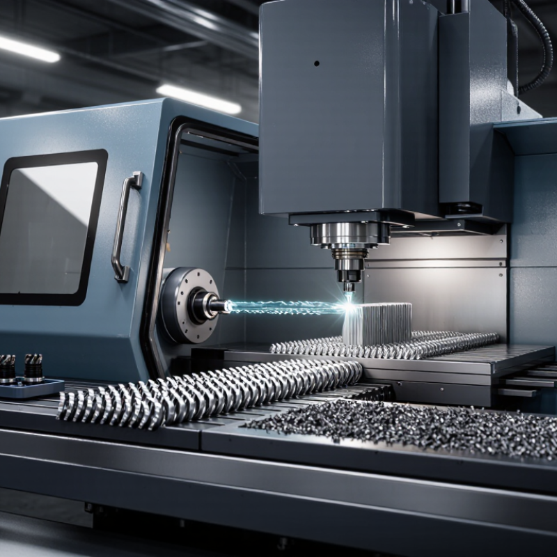
Chip removal efficiency describes how reliably a cutting process clears generated chips from the cutting zone. It is not a single universally standardized percentage. A practical shop-floor measure compares chips captured or discharged with chips generated over a defined time. For example, an illustrative production log might record 9 kilograms discharged from 10 kilograms generated: 90% by mass. State the measurement boundary clearly; chips left in a conveyor or piled near the tool can distort the result. Not perfectly.
The figure matters because trapped chips may be recut, scratch a finished surface, or obstruct coolant flow. ISO 3685:1993 sets controlled turning-tool test conditions, including cutting speed, feed, and depth of cut; these variables also shape chip size and evacuation behavior. Track them alongside chip mass, machine stops, and visible recutting. A long spiral wrapping around a workpiece tells a different story from short chips collecting beneath the conveyor. Check coolant direction, nozzle position, conveyor loading, and chip-breaker setup before changing cutting parameters. The measurement still has limits: mixed alloys and wet chips can skew mass readings, so record material and collection conditions.
Chip removal efficiency describes how effectively a machining process removes material while maintaining the required part quality, tool life, and safe chip evacuation. Material removal rate (MRR) measures removal speed; it is not, by itself, a complete measure of efficiency.
| Measure or factor | Meaning / calculation | Practical interpretation | How to improve it |
|---|---|---|---|
| Material removal rate (MRR) | Volume of material removed per unit of cutting time, commonly expressed in mm³/min or cm³/min. | A higher MRR can increase productivity, provided the machine, tool, workpiece, and setup remain within safe limits. | Increase feed, depth of cut, or cutting speed only within suitable tool and process limits; verify surface finish and tool wear. |
| Milling MRR | MRR = axial depth of cut × radial width of cut × table feed. With dimensions in mm and feed in mm/min, the result is mm³/min. | For example, 2 mm × 10 mm × 600 mm/min = 12,000 mm³/min, or 12 cm³/min. | Choose a stable toolpath and suitable engagement; increase feed or cut dimensions incrementally and monitor spindle load and vibration. |
| Turning MRR | For a conventional turning cut: MRR ≈ π × workpiece diameter × spindle speed × feed per revolution × depth of cut. | Use consistent units: diameter, feed, and depth in mm and spindle speed in rev/min give an approximate result in mm³/min. | Select feed and depth of cut to suit the insert and workpiece; check chip control, rigidity, and the required finish. |
| Drilling MRR | MRR = (π × drill diameter² ÷ 4) × axial feed rate. For a constant feed per revolution, axial feed rate = feed per revolution × spindle speed. | This estimates the volume removed during drilling; actual performance also depends on hole depth, chip evacuation, and tool geometry. | Use an appropriate drill and feed, provide suitable coolant or chip-clearing cycles when needed, and avoid packing chips in the hole. |
| Cutting-time utilization | Productive cutting time ÷ total cycle time × 100%. | This indicates how much of the cycle is spent cutting rather than loading, repositioning, measuring, or waiting. | Reduce avoidable tool changes and idle movements, improve setup planning, and use appropriate automation where justified. |
| Chip evacuation | The reliable removal of chips from the cutting zone without recutting, clogging, or damaging the workpiece. | Poor evacuation can cause heat buildup, surface damage, tool wear, or unplanned stoppages—even when calculated MRR is high. | Adjust chip-breaking conditions, coolant delivery, toolpath, and chip-clearing intervals to the operation and material. |
| Quality and tool-life check | Assess MRR alongside dimensional accuracy, surface finish, tool wear, and process stability. | A faster cut is not more efficient if it produces scrap, shortens tool life excessively, or causes frequent interruptions. | Run controlled trials, change one parameter at a time, inspect parts, and compare output per total production time. |
Note: MRR equations are idealized calculations. Actual safe cutting conditions depend on the workpiece material, tool geometry, machine capability, workholding, coolant, and required part quality.
Repeat the same cut with matching material, tool, feed, depth, and coolant settings. Observe where chips collect.
No. Drying and weighing helps, but coolant and chips in hidden spaces affect the estimate.
Look for packed flutes, fresh scratches, rising spindle load, or a rougher surface. None proves the cause alone.
They help reveal patterns across test runs. Note whether chips leave cleanly or cling to the tool.
Use a short video or timed inspection. Keep the measurement method and cutting conditions consistent.
Match feed, speed, and chip-breaker geometry to the material and operation. Small adjustments may help.
No. Aim the flow at the tool edge; extra flow alone may not solve the problem.
Peck cycles or through-tool coolant can help when the setup allows. Check the hole during a short trial.
Check them during routine runs. Packed chips can block drainage and return to the cutting area.
Not quite. Results vary with alloy, tool wear, and machine rigidity, so verify changes before scaling up.
Chip removal efficiency describes how effectively a machining process clears chips from the cutting zone, helping maintain stable cutting conditions and consistent part quality. It can be assessed by observing how quickly and completely chips leave the work area, as well as by monitoring chip buildup, surface finish, tool wear, and interruptions during machining. The results depend on factors such as workpiece material, cutting speed and feed, tool geometry, chip shape, coolant flow, and the design of the machine and workholding.
To assess chip removal, inspect the cutting zone and finished parts, note whether chips become tangled or accumulate, and compare performance under consistent operating conditions. Practical ways to improve chip removal efficiency include choosing cutting parameters that produce manageable chips, selecting suitable tool geometry, directing coolant or air toward the cutting area, and adjusting the machining path to prevent chips from being trapped. Regularly clearing debris and reviewing process results can also reveal where improvements are needed. The best approach balances effective chip evacuation with reliable tool life, surface quality, and productive operation.

 Carto Tool